Magnavox Odyssey projects
The reviews on this site are the text versions of the videos on my YouTube channel. The text based reviews use (if at all) very little pictures. Please follow the link to the corresponding video in order to see in game graphics.
In episode 59 I reviewed the Magnavox Odyssey games compilation Shooting Gallery Targets and the Odyssey light gun Rifletronix. To keep the video in a decent length I did not show much of my own Odyssey projects. The review here has four topics: My reproduction boards, my video modification board, my Pistoltronix light gun and my Odyssey Multi Card.
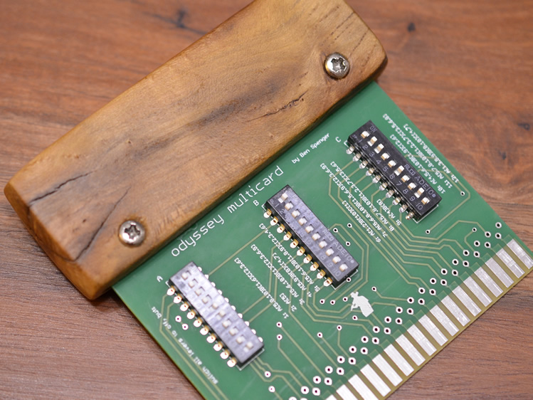
Multicard
I wanted to recreate game cards 9 and 10 which are the light gun cards. While designing I realized that it was silly to make a dual game circuit board which ignores the other 10 games. So I came up with a multi card which allows all twelve Odyssey games to be played. Just read on the PCB the necessary ON/OFF combination, set them and you are good to go. I made a handle out of ivy wood because I like uncommon materials.
Print this with a thickness of 1.55 mm. Just use the layers top(1), bottom(16), pads(17), vias(18), dimension(20), tplace(21), bplace(22), holes(45), tStop(29), bStop(30).
Parts: 10 fold DIL or DIP switch (raster 2,54 mm).
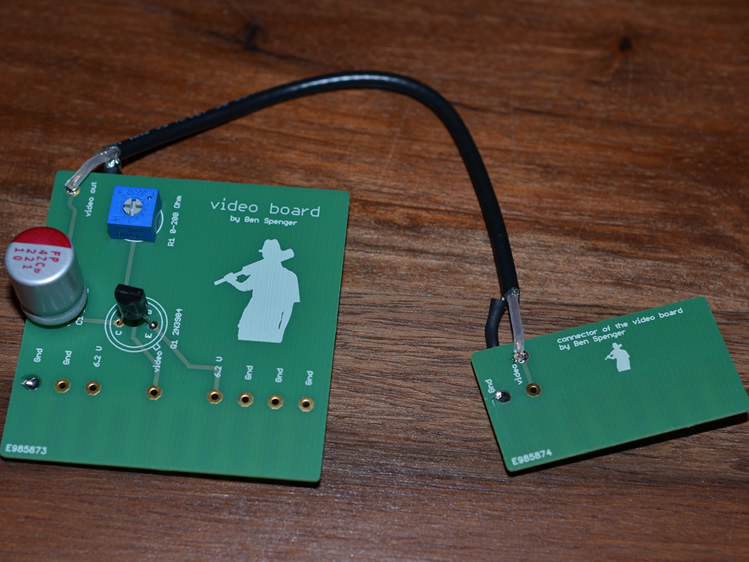
Video Modification
In the Dutch videopac.nl forum the users VideopacBelgium and Rene_G7400 invented a video modification. Personally I wasn't happy with the pad choice and searched other pads for me. While doing so I discovered that the pins of the RF modulator and RF filter sockets can be used for the same task and I came up with my video board. If you want a simple cheap video mod use loose cables as I did for quite some time. My boards are supposed to be used by people who don't want to irreversibly alter a 45 years plus old console. Just plug out the two RF boards, plug in my video board and you are good to go. The video output will now transmit something you can feed into a composite input. The hole in the shield housing allows the players to alter the trim potentiometer setting to find the own sweet spot while the console is hooked up. The additional ground solder pads are for people who prefer to use shielded cables rather than simple wires.
Print this with a thickness of 1.00 mm. Just use the layers top(1), bottom(16), pads(17), vias(18), dimension(20), tplace(21), bplace(22), holes(45), tStop(29), bStop(30).
Parts: C1 220 μF 10 V plus towards signal source; Q1 2N3904 NPN; R1 0-200 Ω trim potentiometer.
Magnavox Odyssey reproduction boards
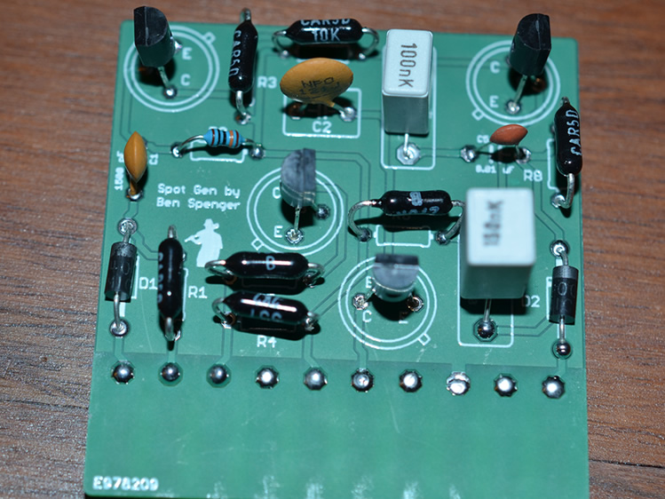
Quite some time ago I bought a broken Odyssey, as they are cheaper than working ones. Sadly mine had one of the spot generating boards missing and the video signal tails to the right. This was my start into the Odyssey. I tried to recreate the missing board, but as the used transistors are well over 45 years old now, I couldn't find information about them. So I isolated a statistically significant number of each kind and measured a set of experiments with each transistor. In some cases this allowed me to choose a modern equivalent transistor as a replacement. Sadly transistors don't last forever. On some kinds of transistors the standard deviation was so high, that I couldn't sanely use my measurements. In those cases I brute force tested transistors from my personal library until I found a suitable one. I then drew my personal spot generator and had it printed by a European company. It worked surprisingly well and was the start to my project ''Ulysses'' in which I recreate the whole system with modern components.
Spot Generator
Print this with a thickness of 1.00 mm. Just use the layers top(1), bottom(16), pads(17), vias(18), dimension(20), tplace(21), bplace(22), holes(45), tStop(29), bStop(30).
Parts: R1 10 kΩ; R2 100 kΩ; R3 10 kΩ; R4 2,2 kΩ; R5 10 kΩ; R6 270 kΩ; R7 10 kΩ; R8 10 kΩ; D1 Schottky 1 A 100 V DO-41 plus towards pin 10; D2 Schottky 1 A 100 V DO-41 plus towards pin 1; Q1 2N3904 NPN; Q2 2N3904 NPN; Q3 2N3904 NPN; Q4 2N3904 NPN; C1 1.5 nF; C2 120 pF; C3 0.15 μF; C4 0.1 μF; C5 10 nF.
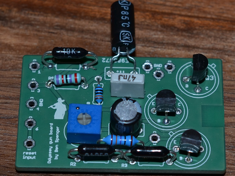
Pistoltronix
I made a Rifletronix board reproduction for people without Odyssey light gun. When playing light guns personally I prefer pistols over rifles. That's why I put it into a pistol to test the board. The reload button is on the handle of the gun, similar as it was with the Namco GunCon 2 which is my favorite light gun to date. My own Pistoltronix ends in a DE-9 socket, as this is what my Ulysses uses. But I can use the Pistoltronix with a real Odyssey by using an adapter.
Print this with a thickness of 1.00 mm or 1.55 mm. Just use the layers top(1), bottom(16), pads(17), vias(18), dimension(20), tplace(21), bplace(22), holes(45), tStop(29), bStop(30).
Parts: R1 237 Ω; R2 10 kΩ; R3 2,2 kΩ; R4 10 kΩ; R9 27 kΩ; R10 100 kΩ; R11 0-2 MΩ trim potentiometer; Q1 2N6426 Darlington NPN; Q2 2N3904 NPN; Q3 2N3904 NPN; LXD6537A-V hermetic CDS LDR; C1 47 μF 16 V plus towards potentiometer; C2 47 63 VDC nF; C3 4,7 μF 50 V plus towards R9.