GameGun to arcade augmenter
The reviews on this site are the text versions of the videos on my YouTube channel. The text based reviews use (if at all) very little pictures. Please follow the link to the corresponding video in order to see in game graphics.
In episode 110 I showed a quick preview of a circuit I have developed which allows people to play American Laser Games arcade games on suitable 3DO machines. The usable 3DO machines either need an additional ROM set, or need to have the RSA check disabled as shown in episode 82.
The starting point for my own measurements was the great documentation the software developer "trapexit" has written for the 4DO emulator. I discovered that the gun message consists of 40 bits. The first 8 bits are the identity tag of the gun which is 0100 1101 corresponding to hex 4D. The following bits control trigger, service button, start and holster in this order. The next two bits are unused. What follows is the light message, which encodes positional information.
For my design I decided to create a new message with the additional information about the buttons which are not present on a stock 3DO GameGun and fuse them with the old message. Many aspects of the circuit are inspired by a Street Fighter controller published by H. Kashima in 1997.
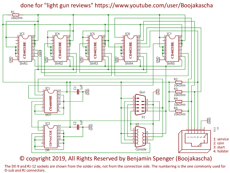
I am using five 8 bit shift registers which are connected in series and are therefore able to create a 40 bits long message. My circuit clocks in 8 μs too late, which is no problem at all, as I don't want to interfere with the first nine bits anyways. But I had to shorten my additional message to 39 bits because of this. The physical location of the registers is inverted relative to their output in time space. Therefore I had to use the second last chip, to interfere with the second 8 bit data package.
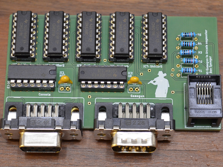
Compared to my prototype the finished circuit is much tidier. The board is powered over the left most connector which is connected to the console. The GameGun is connected into the middle socket. I chose to use a RJ-12 socket to connect up a soap box which houses the necessary additional buttons. I designed the board in such a way that standard DE-9 prolongation cables and straight serial cables can be used. When using serial cables, usually the screws have to be cut away, as they would collide with the 3DO.
As usually I uploaded the PCB files onto my website for everybody to use for non-profit purposes. If you plan to print these and resell them, make sure you are doing it for the cost of materials. Else contact me.
Print this with a thickness of 1.55 mm. Just use the layers top(1), bottom(16), pads(17), vias(18), dimension(20), tplace(21), bplace(22), holes(45), tStop(29), bStop(30).
Parts: R1-5: 10 kΩ; C1-2: 1 μF; IC1: CD4069BE CMOS Hex inverter; IC2: CD74AC32E quadruple 2-input positive-OR gates; IC1-5: CD4021BE Hex CMOS 8-stage static shift registers
